
TM 5-5420-202-20-3
FENDER SUPPORT NO. 4 (LEFT AND RIGHT) REPLACEMENT (Sheet 1 of 4)
PROCEDURE INDEX
PAGE
PROCEDURE
Removal
Cleaning and Inspection
Installation
TOOLS: Ratchet with 1/2 in. drive
1 in. socket with 1/2 in. drive
1-1/8 in. socket with 1/2 in. drive
Hinged handle with 1/2 in. drive
7/8 in. socket with 1/2 in. drive
9/16 in. socket with 1/2 in. drive
3/4 in.socket with 1/2 in. drive
3/4 in. combination box and open end wrench
Torque wrench with 1/2 in. drive (0-175 lb-ft)
5/8 in. socket with 1/2 in. drive
7/8 in. combination box and open end wrench
SUPPLIES:
Lockwashers (4 required)
Locking compound (Item 15, Appendix D)
PRELIMINARY
PROCEDURES:
Remove rear fender stowage box (page 16-84)
Remove fender extension (page 16-65)
Remove air cleaner (page 7-90)
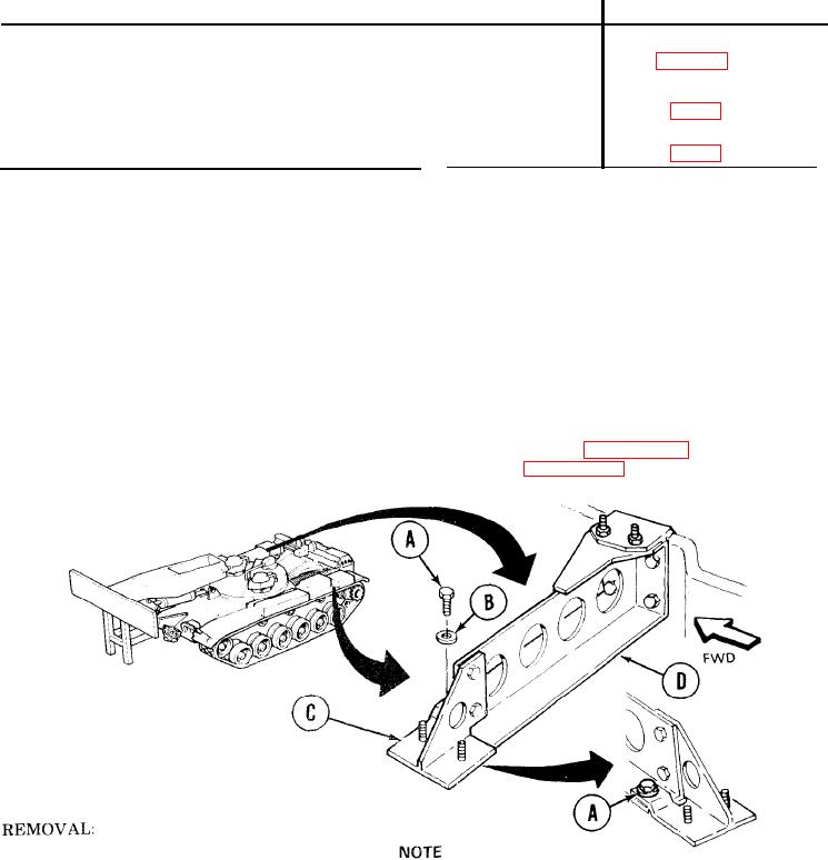
Left No. 4 fender support is shown; right No. 4 fender support replacement is
similar.
1.
Using 5/8 inch socket, remove screw (A) and flat washer (B) holding extension bracket (C)
to bottom flange of No. 4 fender support (D).
TA249727
Go on to Sheet 2