TM 5-5420-202-34
TRACK ADJUSTING LINK REPAIR (Sheet 9 of 13)
NOTE
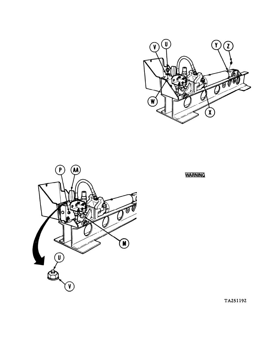
Relief valve (U) used in next step
was removed from track adjusting
link yoke at disassembly.
Install new packing (V) on relief valve
11.
assembly (U). Coat threads of valve assem-
bly (U) with grease.
Using 15/16 inch socket and torque wrench,
12.
install valve assembly (U) into manifold
block hole (W) and tighten to 40-60 lb-ft
(54-81 Nm).
Using grease gun, pump grease into fitting
13.
(X) until grease comes out pipe plug hole
(Y) on end of adjusting link. Using 3/8
inch wrench, install and tighten pipe plug (Z).
Wear goggles and cover relief valve with
a rag to prevent grease from getting in
eyes. Relief valve opens at 2150-2250 psi
and blows a fine spray of grease.
Watch gage (AA) and pump grease into
14.
manifold grease fitting (P) until relief
valve (U) opens between 2150 and 2250
psi. If valve (U) opens between 2150 and
2250 psi, turn needle valve handle (M)
counterclockwise to release pressure,
remove valve (U) and packing (V), throw
packing (V) away, and go to step 15. If
relief valve (U) does not open between
2150 and 2250 psi, turn needle valve handle
(M) counterclockwise to relieve pressure,
remove valve (U) and packing (V), throw
away valve (U) and packing (V), install
new valve (U) and new packing (V) (steps
11 and 12), and repeat this step.
Go on to Sheet 10
9-37


