ARMY TM 5-5420-212-10-1
MARINE CORPS TM 08676A-10/1-1
4-1.
INTRODUCTION
This chapter describes the general drills used during assembly/disassembly of SS, DS and LR MGB.
These drills are used repetitively so it is important that the operator becomes familiar with them before attempting
to carry out the step by step procedures described in Chapters 5, 6 and 7. Most of the drills describe the assembly or
connection of components; unless otherwise stated, the disassembly or disconnection drill
is the reverse procedure.
4-2.
PANEL POINT CODE AND CENTER OF GRAVITY
a.
Single Story
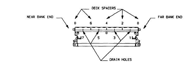
The panel point code is a system of numbering used to identify the location of the center of gravity (C of G) and
the boom and launch points of the bridge. The numbering is based on the top panels, their deck spacers and drain holes.
The top panel numbering starts at the top panel next to the far bankseat beam. The panel point numbering begins at the
front of the top panel i.e. the end closest to the far bank. One panel point (1 pp) means 1/8 of a bay = 9 in (229 mm).
(1)
Top panel. The top panels in the bays of the bridge are numbered 1, 2, 3, 4, 5, etc.
(2)
Top panel deck spacers. The deck spacers are panel points 2, 4 and 6. The deck spacer at the rear of the
top panel becomes panel point 0 of the next panel or bay.
(3)
Drain holes. The drain holes halfway between each deck spacer, are panel points 1, 3, 5 and 7.
4-2


