ARMY TM 5-5420-212-10-1
MARINE CORPS TM 08676A-10/1-1
(1)
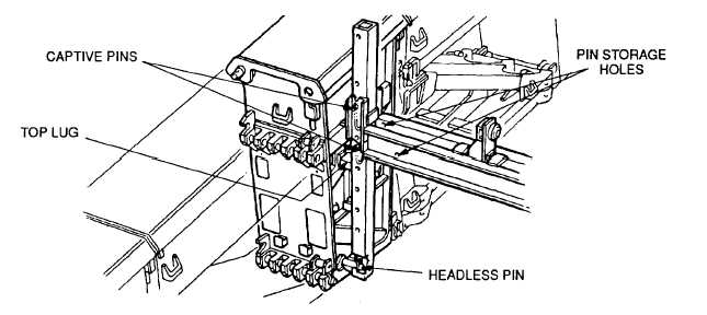
Remove the inside retainer clip from headless pins at junction of bays 2 and 3.
(2)
Fit nose cross girder posts to the headless pins at junction of bays 2 and 3. Center lug of post connects to
the compression faces of the two top panels.
(3)
Put retainer clip back onto headless pin. This will keep the nose cross girder post from slipping off headless
pin.
(4)
Slide launching nose cross girder up posts to correct setting (para. 4-11c.). Insert captive pin in lower hole
position determined by design.
(5)
Lower post jaw onto captive pin then insert top pin in top pin hole.
(6)
Put retainer clips through end of captive pins.
(7)
After the bridge is launched remove the assembly by:
(a)
Reposition the deck unit next to the launching nose cross girder and posts.
(b)
Support launching nose cross girder on both sides of bridge and remove captive pins (place captive pins
in storage holes).
(c)
Raise girder until it clears posts and place it on the deck unit.
(d)
Remove clip from headless pin.
(e)
Remove posts.
(f)
Carry the launching nose cross girder to the end of the bridge.
b.
Double Story
(1)
Put a headless pin into the pin hole in the junction panel.
(2)
Place the launching nose cross girder post onto the junction panel top lug, then over the headless pin.
4-34


