ARMY TM 5-5420-212-10-1
MARINE CORPS TM 08676A-10/1-1
(13) Add fourth (4N1) and fifth (5N1) nose sections, booming nose forward and securing with panel pin as
each is added.
NOTE
The rear bankseat beam is connected to top panels in the following step, and is part of the
counterweight used in the assembly of the longer launching nose.
(14) Unlock roller beam under one girder to ease next operation.
(15) Connect bankseat beam to top panels of bay 4, with shootbolts only.
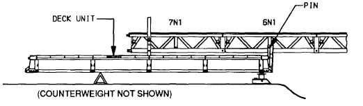
(16) Add sixth (6N1) and seventh (7N1) nose sections.
WARNING
In following step bridge will tip as nose is boomed forward. Crew must hold rear of bridge down
until step (20).
(17) Boom nose forward until anchorage tube of nose section 6N1 aligns with holes in nose roller.
(18) Put panel pin through nose roller and anchorage tube, then insert retainer clip through panel pin.
(19) Place one deck unit in third deck recess of bay 3.
(20) Set up landing roller pedestal (para. 4-15a.).
(21) To remove counterweight.
(a)
Remove counterweight deck and top panels to allow launching nose to set down onto landing roller
pedestal.
(b)
Far bank crew guide nose onto landing roller pedestal.
(c)
DO NOT remove bankseat beam.
(22) Remove building pedestals.
(23) Unlock rollers and boom to panel point 2p7. Lock rollers.
5-34