ARMY TM 5-5420-212-10-1
MARINE CORPS TM 08676A-10/1-1
(d)
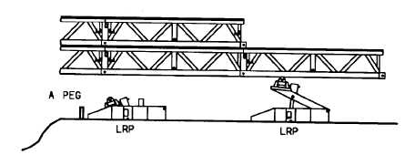
Operate hydraulic jack to lift the launching nose off of the packing and nose section.
(e)
Remove packing and nose section from under launching nose.
(f)
Position second landing roller pedestal under launching nose with base against original A peg.
(g)
Operate jack in landing roller pedestal to raise launching nose off of first landing roller pedestal.
Lower first landing roller pedestal and remove from under launching nose.
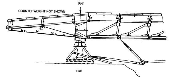
(18) Raise capsill roller beam until weight of bridge is on capsill roller beam and off ex FRB. Continue raising
to maximum height 4.1 ft (1.3 m) and level capsill roller beam at maximum height. When raising capsill
roller beam, if jacks have to be restaged, jack seat must be placed on capsill pin in holes 1, 2 or 3. Do
not put jack seat on pin in holes 4, 5 or 6.
(19) Remove ex FRB from under bridge.
(20) Delaunch bridge until Dp2 is over capsill roller beam.
(21) Place timber packing (3 in x 8 in x 84 in) over capsill roller beam cross girder and remove long link fork
end anchors from bottom panel pin at Dp0. Lower long link onto packing and place fork end anchors in
their stowed position but do not secure with bracing pins until step (23) to prevent them fouling on CRB.
(22) If not previously done so at step (14), add launching nose heavy section 5N1.
(23) Delaunch bridge to 22p2 (over CRB). Lock rollers. Secure anchor assembly long link fork end anchors
in their stowed position with bracing pin and retainer clip.
7-28


