ARMY TM 5-5420-212-10-1
MARINE CORPS TM 08676A-10/1-1
7-2.
DISASSEMBLY - 2E + 22 BAY LINK REINFORCED
a.
Preparation for Disassembly
(1)
If pumps, hoses and water are available, the bridge, erection and link components should be washed
before loading them on to pallets.
(2)
If washing cannot be done, the components are loaded directly onto pallets.
b.
Disassembly
NOTE
Throughout bridge disassembly the NCOIC must monitor the height and level of the roller beams.
The height must be set to achieve an acceptable working height. Roller beams must be level so
that components connect/disconnect properly.
(1)
Remove bridge classification signs, bridge guide markers and curbs (reverse of para. 4-26). Retain six
curbs on the near bank end of bridge as part of counterweight [see step (4)].
(2)
Remove far bank ramp units, removing center ramp first (reverse of para. 4-24).
(3)
Operate cable pullers on post tensioners to release tension in link chain, then use light tackle to raise
link chain [reverse of para. 4-16e. and d. step (4)].
(4)
Remove deck units (reverse of para. 4-25) starting on the far bank end of bridge as follows:
(a)
Leave a deck unit in the third recess of bays 1, 7, 11, 17, and 21.
(b)
Leave both bays of near end of bridge fully decked (eight deck units).
(c)
Leave thirty two deck units (this makes a total of forty) and six curbs in the bridge to be used as
counterweight after step (10).
(5)
Add launching nose cross girder and posts (para. 4-11b) on far bank junction panel.
(6)
Remove near bank ramp units, removing center ramp first (reverse of para. 4-24).
(7)
Raise near bank end of bridge using jacks, davits or crane, high enough to install a roller beam (ex
FRB).
(8)
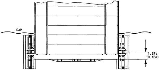
Install ex FRB centered on bridge and a minimum 1.5 ft (0.46 m) from outside of bankseat beam.
7-25


