
3TM 5-5420-226-20-2
ENGINE ACCESS COVERS (RIGHT BANK) REPLACEMENT (Sheet 5 of 5)
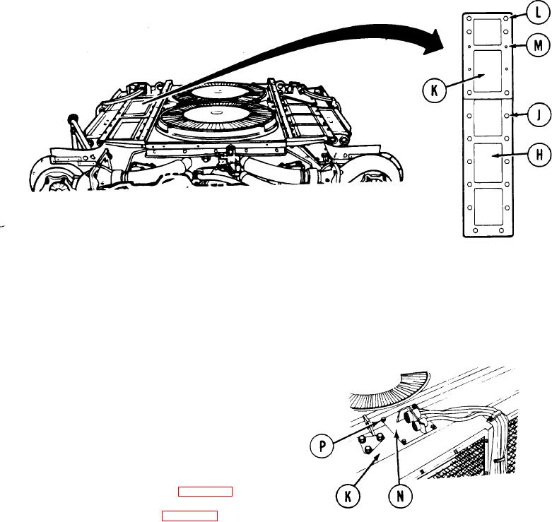
P o s i t i o n rear engine access cover (H) in place on engine.
9.
10.
I n s t a l l 12 screws and washers (J). Do not install screws in last holes toward front of
e n g i n e . U s i n g socket, tighten 12 screws (J).
P o s i t i o n front engine access cover (K) in place on engine.
11.
I n s t a l l six screws and washers (L). Do not install screw in t h e four holes (M). Using
12.
s o c k e t , tighten six screws (L).
Position date with electrical connector (N)
13.
o n front engine access c o v e r ( K ) . A l i n e
s c r e w holes in plate (N) with those in front
e n g i n e access plate (K).
I n s t a l l four screws and washers (P) to secure
14.
p l a t e t o s h r o u d . U s i n g socket, tighten four
screws ( P ) .
I n s t a l l engine shroud (page 9-31).
15.
I n s t a l l powerplant (page 5-14).
16.
TA107578
End of Task
6-111