
TM 5-5420-226-20-2
ENGINE FUEL RETURN HOSE ASSEMBLY (LEFT SIDE) REPLACEMENT (Sheet 2 of 2)
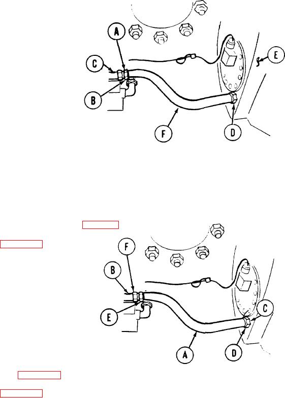
REMOVAL:
1.
Using one 1-1/2 inch wrench to hold fitting (A),
use other 1-1/2 inch wrench and loosen fitting (B)
from elbow (C).
2.
Using 1-3/8 inch wrench, loosen fitting (D)
from fuel tank (E).
Carefully remove hose (F) from elbow
3.
and fuel tank (E).
INSTALLATION:
CAUTION
Make sure that drain plugs of
both fuel tanks are correctly
sealed.
Lightly coat threads of each hose end fitting with
1.
sealing compound.
Position hose (A) onto elbow (B) and fuel tank mount (C).
2.
Using 1-3/8 inch wrench, tighten fitting (D) to fuel tank
3.
mount (C).
Using one 1-1/2 inch wrench to hold fitting (E), use
4.
other 1-1/2 inch wrench and tighten fitting (F) to elbow (B).
Install engine fuel return hose assembly (page 7-1 62).
5.
6.
Ground hop engine (page 5-25).
Allow engine to run for a brief time while checking for leaks.
7.
If a leak is detected, stop engine and tighten fittings.
Disconnect ground hop (page 5-40).
8.
Install powerplant (page 5-14).
9.
TA107767
End of Task
7-160