
TM 5-5420-226-20-2
TURBOCHARGER SHROUDS REPLACEMENT (Sheet 3 0f 6)
Inner Shroud Replacement (Sheet 3 0f 4)
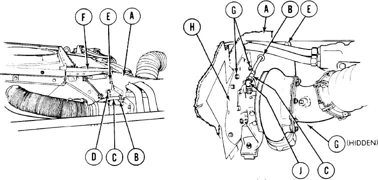
INSTALLATION:
P l a c e inner shroud (A) into position.
1.
2.
I n s t a l l grommet (B) on hose assembly (C).
I n s t a l l grommet (B) and hose assembly (C) in inner shroud (A).
3.
I n s t a l l three screws and washers (D) securing inner shroud (A)
4.
t o oil cooler frame.
I n s t a l l screw, lockwasher, and nut (E) to secure inner shroud
5.
..
(A) to upper shroud (F).
I n s t a l l four screws and washers (G) securing inner shroud (A)
6.
to turbocharger plate (H).
U s i n g 1/2 inch socket, tighten four screws (G).
7.
U s i n g 1 / 2 i n c h s o c k e t w i t h extension, tighten three screws
8.
(D).
U s i n g 1 / 2 i n c h s o c k e t a n d 1/2 inch wrench, tight en screw and
9.
nut (E).
C o n n e c t hose assembly (C) to elbow (J). Using 11/16 inch wrench,
10.
t i g h t e n hose assembly-(C) onto elbow (J).
TA107998
Go on to Sheet 4
9-43