
TM 5-5420-226-20-2
TURBOCHARGER SHROUDS REPLACEMENT (Sheet 6 0f 6)
Upper Shroud Replacement (Sheet 1 of 1)
TOOLS:
l / 2 i n . combination box and open end wrench
l/2in. socket with l/2 in. drive
5 i n . extension with l/ 2in. drive
R a t c h e t with l/2 in. drive
Remove powerplant (page 5-2).
PRELIMINARY
PROCEDURES:
R e m o v e rear engine shroud support (page 9 - 3 9 ) .
NOTE
Procedures for replacement of the left or right
transmission shrouds are similar. Procedures
for the left side are shown.
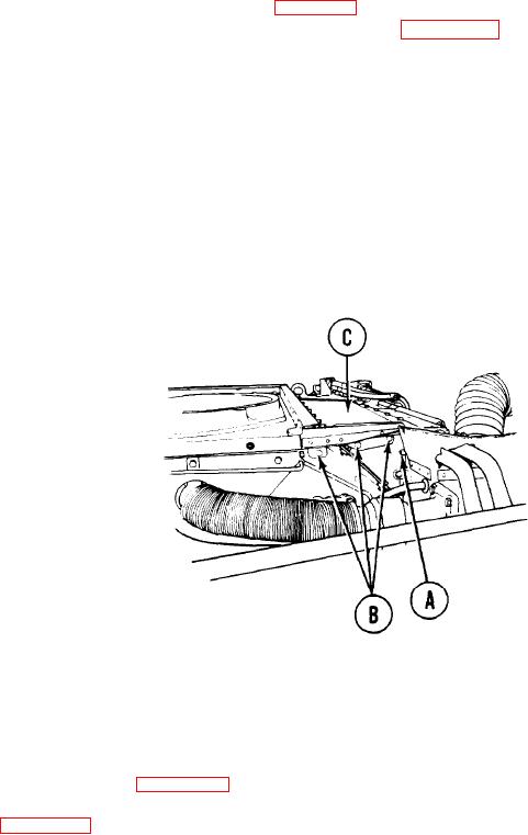
REMOVAL:
1.
Using 1/2 inch socket with extension and 1/2 inch wrench, remove screw, lockwasher,
and nut (A).
2.
Using 1/2 inch socket with extension, remove three screws and lockwashers (B).
3.
Remove upper shroud (C).
INSTALLATION:
P o s i t i o n upper shroud (C) in place.
1.
2.
I n s t a l l three screws and washers (B).
3.
I n s t a l l screw, lockwasher, and nut (A)..
U s i n g 1/2 inch socket with extension and 1/2 inch wrench, tighten screws (A and B).
4.
5.
I n s t a l l rear engine shroud support (page 9-40).
6.
Install powerplant (page 5-14),
TA108000
E n d of Task