
TM 5-5420-226-20-2
COOLING FAN SHROUD REPLACEMENT (Sheet 6 0f 8)
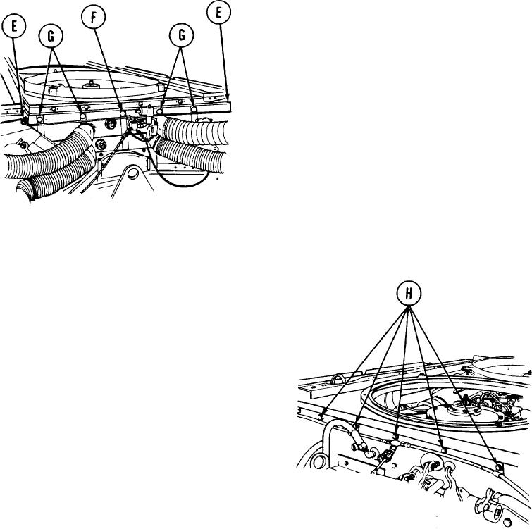
5.
U s i n g 1/2 inch socket, install two screws
( E ) securing shroud and fuel line clamps
to engine.
6.
U s i n g 1/2 inch socket, install one screw
( F ) securing shroud to engine.
7.
U s i n g 1/2 inch socket, install four screws
( G ) securing shroud to engine.
8.
P o s i t i o n clamps on fuel line, located
o n underside of shroud, onto screws
( G ) . Using 1/2 inch wrench, install four
n u t s onto screws (G) securing fuel line
clamp.
REAR OF ENGINE
9.
Using 1/2 inch socket, install five screws
( H ) securing clamps and engine shrouds
t o fan shrouds.
FRONT OF ENGINE
Go on to Sheet 7
TA108006
9-52