
TM 5-5420-226-20-2
COOLINGFAN SHROUD REPLACEMENT (Sheet 3 0f 8)
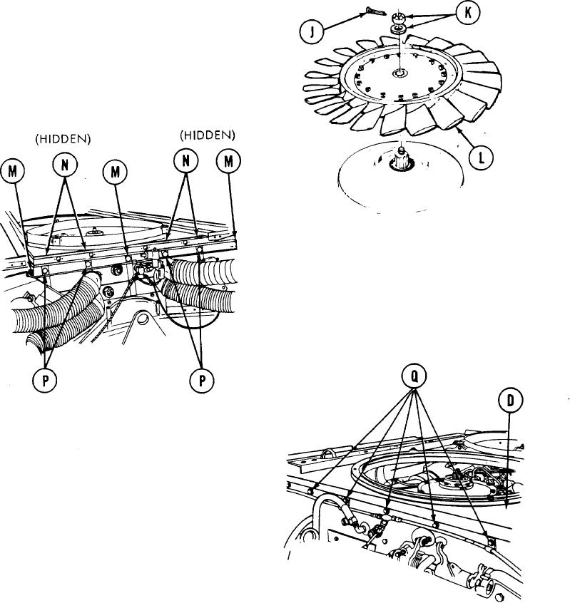
U s i n g pliers, remove cotter pins (J)
8.
f r o m nuts (K) from each fan (L). Throw
c o t t e r pins away.
Using 1-1/4 inch socket, remove nut
9.
a n d washer (K) securing each fan (L)
to engine.
L i f t fans (L) from engine.
10.
NOTE
Four nuts (N) are located under fan
shroud and hold fuel line clamps. When
nut (N) and screws (P) are removed,
clamps will remain on fuel line.
Using 1/2 inch socket, remove three
11.
screws (M).
u s i n g 1/2 inch wrench to hold nuts (N),
12.
u s e 1/2 inch socket and remove four
s c r e w s (P) and nuts (N).
13.
Using 1/2 inch socket, remove five screws
( Q ) securing shroud (D) to engine.
FRONT OF ENGINE
TA108003
Go on to Sheet 4
9-49