
TM 5-5420-226-20-3
SHIFT LINKAGE ADJUSTMENT (Sheet 9 of 28)
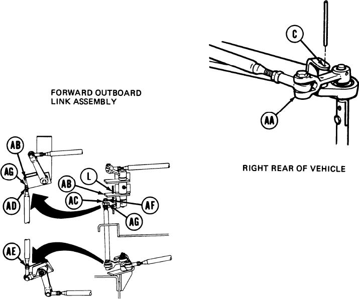
39.
Go to right rear of vehicle and try to
insert locating pin into alinement hole (C)
and through clevis (AA). If locating pin
can be inserted, shift linkage is in adjust-
ment. Remove locating pin and go to step
125. If locating pin can not be inserted,
go on to step 40.
Try to insert locating pin (L) into alinement
40.
holes in support (AB) and link (AC). If
locating pin (L) can be inserted, remove
locating pin (L) and go to step 68. If locating
pin (L) cannot be inserted, go on to step 41.
FORWARD INBOARD
41.
Using 9/16 inch wrench, loosen jamnuts
LINK ASSEMBLY
(AD) and (AE).
42.
Using 9/16 inch wrench, remove screw (AF)
and remove shifting rod bearing end (AG)
from clevis (AC).
43.
Manually move clevis (AC) and insert locating
pin (L) into alinement holes in support (AB)
and link (AC).
Go on to Sheet 10
TA169062
11-61