
TM 5-5420-228-24
HOLD DOWN CYLINDER HOSE ASSEMBLIES (CU1 CU2, CV1 THRU CV4) AND HYDRAULICS
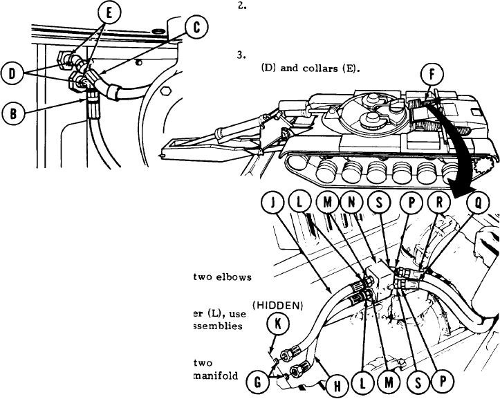
REPLACEMENT (Sheet 2 of 5)
Using adjustable wrench to hold two elbows
(D), use 7/8 inch wrench to disconnect hose
assemblies "CU1" (B) and "CU2" (C).
Using adjustable wrench, remove two elbows
4.
O p e n right side grille doors (F) (TM 5-
5420-202-10).
5.
Using adjustable wrench on elbows (G), use
7/8 inch wrench to disconnect hose assembly
"CVI" (H) and "CV2" (J).
Using adjustable wrench, remove
6.
(G) and collars (K).
7.
Using 13/1 6 inch wrench on adapt
7/8 inch wrench to remove hose a
"CV1" (H) and "CV2" (J).
Using 13/1 6 inch wrench, remove
8.
adapters (L) and collars (M) from
(N).
Using adjustable wrench on elbows (P), use 7/8 inch wrench to disconnect hose assemblies
9.
"CV3" (Q) and "CV4" (R).
10.
Using adjustable wrench, remove two elbows (P) and collars (S) from manifold (N).
Go on to Sheet 3
TA251571
3-174