
TM 5-5420-228-24
HOLD DOWN CYLINDER HOSE ASSEMBLIES (CU1, CU2, CV1 THRU CV4) AND HYDRAULICS
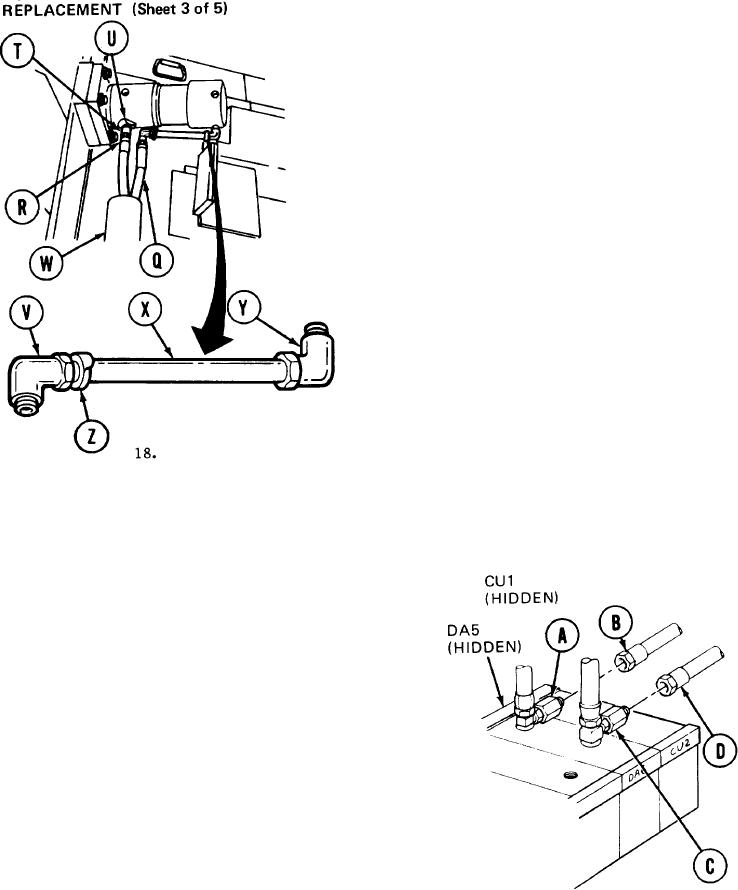
Using 13/16 inch wrench on adapter (T), use
11.
7/8 inch wrench to remove hose assembly
"CV4" (R).
12.
Using 13/16 inch wrench, remove adapter
(T) and collar (U).
Using adjustable wrench on elbow (V), use
13.
7/8 inch wrench to remove hose assembly
"CV3" (Q).
Remove hose assemblies (Q) and (R) from
14.
armor (W).
15.
Using adjustable wrench, remove elbow (V)
nipple (X), and elbow (Y) as an assembly.
Place nipple (X) in a vise.
16.
17. Using adjust able wrench, remove elbow (Y).
(x).
Using adjustable wrench, remove elbow (V) and collar [Z) from nipple
INSTALLATION:
NOTE
Remove caps and plugs as necessary during installation.
Before installation, use pipe tape on all male threads. Start
tape on second thread so tape will not enter hydraulic
system.
Holding adapter (A) with 1-1/4 inch wrench,
1.
use 7/8 inch wrench to connect hose
assembly "CU1" (B).
Holding adapter (C) with 1-1/4 inch wrench,
2.
use 7/8 inch wrench to connect hose
assembly "CU2" (D).
TA251572
Go on to Sheet 4