
TM 5-5420-228-24
HOLD DOWN CYLINDER HOSE ASSEMBLIES (CU1, CU2, CV1 THRU CV4) AND HYDRAULICS
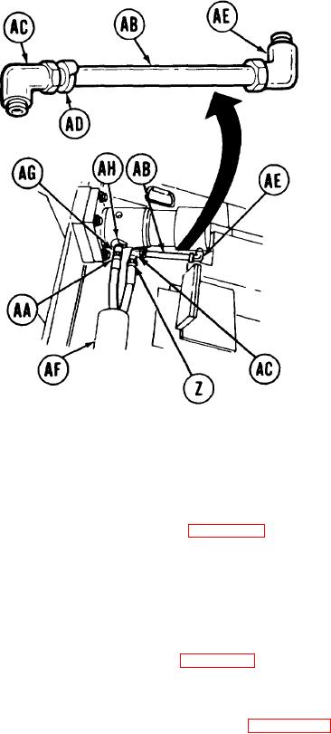
REPLACEMENT (Sheet 5 of 5)
15.
Place nipple (AB) in vise.
16.
Using adjustable wrench, install elbow (AC)
and collar "CV3" (AD) on nipple (AB).
17.
Using adjustable wrench to install elbow
(AE) on nipple (AB). Aline elbows facing
in opposite directions as shown.
18.
U s i n g adjusable wrench, install elbow
(AC), nipple collar (AD], nipple (AB), and
Aline as
elbow (AE) as an assembly.
shown.
19.
Insert hose assemblies "CV3" (Z) and "CV4"
(AA) through armor (AF).
Using adjustable wrench on elbow (AC), use
20.
7/8 inch-wrench to install hose assembly
"CV3" (z).
Using 13/16 inch wrench, install adapter (AG) and collar "CV4" (AH).
21.
Using 13/16 inch wrench on adapter (AG), use 7/8 inch wrench to install hose assembly
22.
"CV4" (AA).
Bleed hydraulic system (page 3-72).
23.
24.
Check for hydraulic leaks and correct as necessary.
25.
Service hydraulic reservoir (LO 5-5420-202-12).
26.
Close right side grille doors (TM 5-5420-202-10).
Install front quadrant (page 3-46) "CU1" and "CU2" hose assemblies only.
27.
28.
Install powerplant (TM 5-5420-202-20) "CV1" and "CV2" hose assemblies only.
29.
Install holddown cylinder armor (page 3-253) "CV3" and "CV4" hose assemblies only.
End of Task
TA251574
3-177