
TM 5-5420-228-24
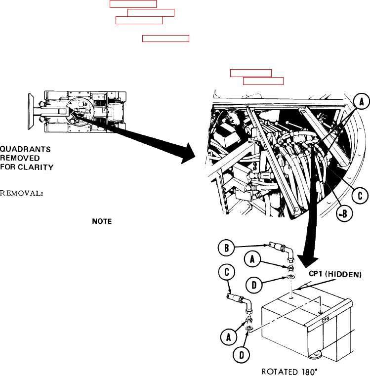
EJECTION CYLINDER HOSE ASSEMBLIES (CP1 AND CP2) AND HYDRAULIC REPLACEMENT
(Sheet 1 of 2)
TOOLS: 7/8 in. combination wrench
11/16 in. open end wrench
12 in. adjustable wrench
1-1/4 in. open end wrench
SUPPLIES:
Drip pans (suitable containers)
Rags (Item 12, Appendix D)
Pipe tape (Item 19, Appendix D)
Pencil (Item 22, Appendix D)
Preformed packing (4 required)
Masking tape (Item 18, Appendix D)
REFERENCE:
LO 5-5420-202-12
PRELIMINARY PROCEDURES:
Remove front quadrant (page 3-45)
Relieve hydraulic pressure (page 3-71)
Use rags and drip pans to catch excess hydraulic
fluid. Use masking tape to tag lines for installation.
1.
Using 1-1/4 inch wrench to hold adapters
(A), use 11/16 inch wrench to remove two
hose assemblies "CP1" (B) and "CP2" (C).
2.
U s i n g 1-1/4 inch wrench, remove two
adapters (A) and preformed packings (D).
Throw preformed packings (D) away.
Go on to Sheet 2
TA251575