
TM 5-5420-228-24
CLUTCH ASSEMBLY REPLACEMENT AND REPAIR (Sheet 7 of 9)
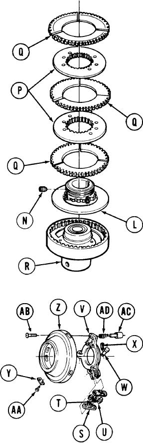
11.
Using 1/4 inch screw key, loosely install
setscrew (N) so it is below thread level
of hub and backplate (L).
12.
Manually install hub and backplate (L),
two clutch discs (P), and three friction
linings (Q) on clutch spider assembly (R)
in order shown.
Assemble six levers (S), three springs (T),
13.
and six pins (U) into three assemblies as
shown.
14.
Place three assemblies in position on yoke
(v).
15.
Install three pins (W) securing three
assemblies to yoke (V).
16.
Using pliers, install three cotter pins
(X) through pins (W).
NOTE
Do steps 17 and 18 ifidentification plate was
removed.
Place plate (Y) in position on cover (Z).
17.
18.
Using hammer, tap in two new drive screws
(AA).
19.
Using flat-tip screwdriver, install three
screws (AB) securing cover (Z) to yoke (V).
Place pin (AC) and spring (AD) in position
20.
through yoke (V) and cover (Z).
21.
Manually pull out on pin (AC) and lock in
place by pushing locating pin through
hole in pin (AC).
TA251690
Go on to Sheet 8
4-39