
TM-5-5420-279-10
4.9.1.14
Disconnect the slings and tag lines from the far bank end beam.
4.9.1.15
Operate the lift and traverse controls on the crane and position the crane to lift the
near bank end beam from the flatrack T1.
4.9.1.16
Connect a tag line to the home bank end beam.
4.9.1.17
Operate the lift and traverse controls on the crane and lift the near bank end beam
from flatrack T1 into position on the ground between flatrack T1 and flatrack V1.
4.9.1.18
Remove the wooden blocks from flatrack T1 and place on the ground.
4.9.1.19
Remove the tag lines from the home bank end beam.
4.9.1.20
Operate the lift and traverse controls on the crane and position the crane to lift the
module lifting beam from flatrack LVT.
4.9.1.21
Attach the single leg-lifting sling to the crane hook and connect the sling to the
module lifting beam.
4.9.1.22
Operate the lift controls on the crane and lift the module lifting beam so that it can be
adjusted to its widest setting.
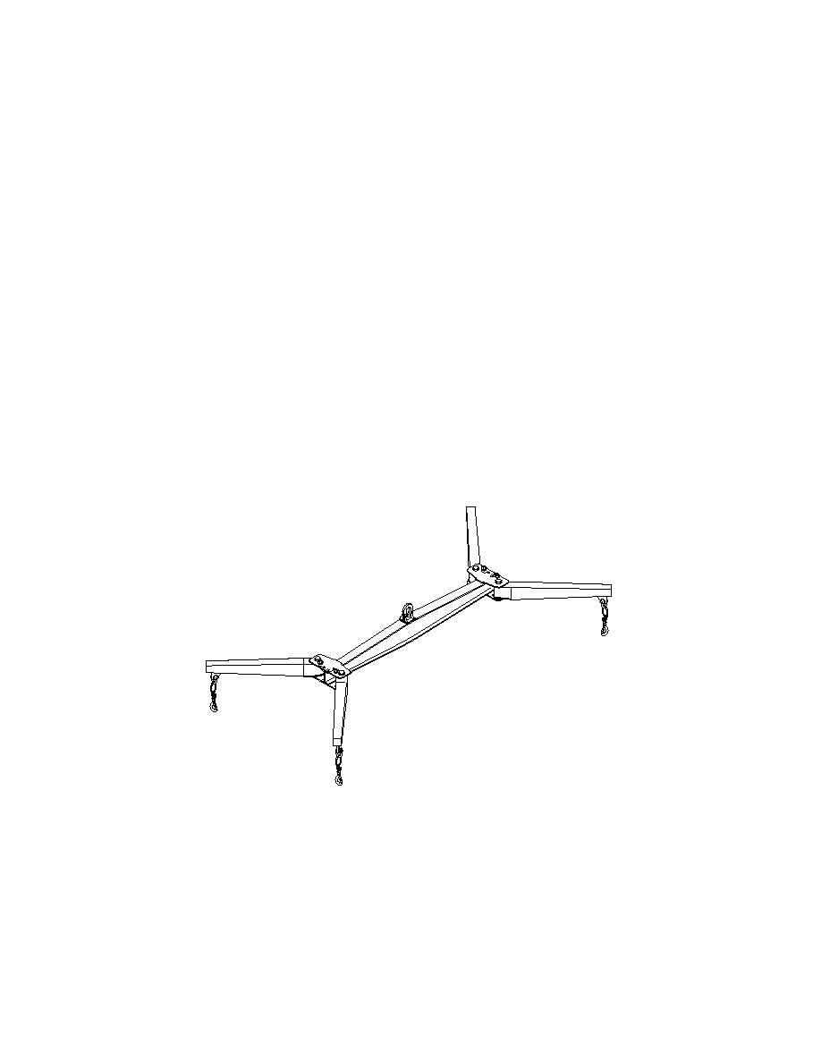
4.9.1.23
Adjust the module lifting beam to its widest setting. Ensure that all the shootbolts are
fully inserted and locked.
686A388a
Module Lifting Beam In Widest Position (Opening Modules)
Figure 4. 11 Module Lifting Beam
4.9.1.24
Operate the lift and traverse controls on the crane and position the crane to lift the far
bank ramp module from the flatrack V1.
4-51
