TM-5-5420-279-10
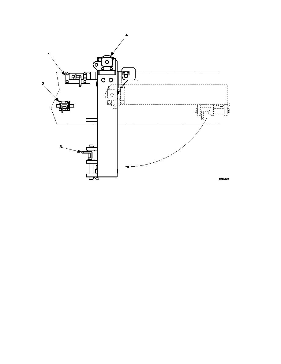
Figure 5. 5 Tilt Roller Shootbolt Positions
NOTE
The tilt rollers adjust the module approach angle required, to compensate for the launch
beam angle created by the up/down slope of the banks, and ensure the correct tension is
maintained on the far bank carriage slings.
If the tilt rollers do not raise, switch the roller brakes on and then off and retry the tilt
rollers.
5.4.4.6
Using the tilt roller joystick on the left of the chest pack raise the tilt rollers to contact
the underside of the bridge.
Recovering the 4th and 5th Parallel Modules
5.4.5.1
On the chest pack, make sure the BRIDGE DRIVE function is selected.
5.4.5.2
Make sure the POWER and the bridge drive mode previously selected captions
(LEVEL, HIGH or LOW) on the chest pack display are illuminated.
5.4.5.3
On the chest pack, move the right hand joystick rearward to reverse the bridge
towards the launch vehicle.
5.4.5.4
Hold down the bridge stops emergency once the jaws of the module are within 12
inches of the bridge stops emergency rollers. Release the bridge stops emergency
as soon as the module jaws are clear of the bridge stops emergency rollers.


