
TM-5-5420-279-10
5.4.5.9
On the chest pack, during module disconnection, hold the tilt roller joystick forward
until the module is fully disconnected.
5.4.5.10
Operate the controls on the crane until the shootbolts can be retracted.
5.4.5.11
Disengage the shootbolts from the parallel modules.
5.4.5.12
Guide the parallel module away from the still connected module. Place the bridging
pins in the inner jaws of both modules from the inside out and retain them with their
R clips.
5.4.5.13
On the tail lift pendant, operate the LIFT DOWN switch to lower the pinning
operatives to the ground.
5.4.5.14
Operate the lift and traverse controls on the crane. Position the parallel module on
the already stacked parallel module on flatrack T2 so that it is at 90 degrees to the
stacked module.
5.4.5.15
Disconnect the bridge module lifter from the lifting points on the outboard sides of
the parallel module.
5.4.5.16
Adjust the bridge module lifter to its middle setting and secure it in position with the
shootbolts.
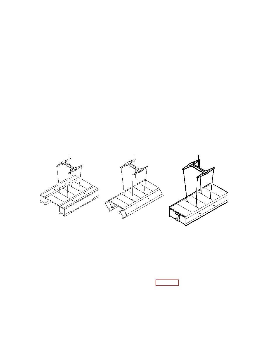
686A659
686A659b
686A659a
Sequence of Closing Bridge Module
5.4.5.17
Connect the bridge module lifter to the steel wire ropes located between the deck
units of the parallel module.
NOTE
When one module is stacked on top of another, transport aids are fitted to the lower
module between the deck units where the wire-closing slings are accessed. The bracket
is fitted with the white edges facing up and out (refer to Figure 5. 4).
5.4.5.18
Remove any debris or stones from the hinge lines of the parallel module.
5-26
