
TM 5-5420-226-20-3
BRAKE PRESSURE GAGE, TUBE ASSEMBLY, REDUCER, AND GASKET REPLACEMENT
(Sheet 5 of 7)
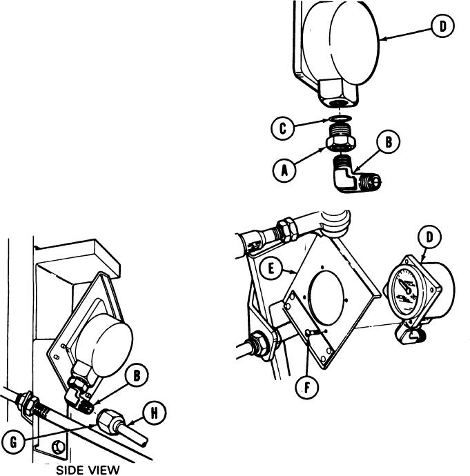
INSTALLATION:
1.
Using fingers, install nut (A) to elbow (B). Install packing (C) above nut (A) and install
elbow (B) to gage (D).
Using 11/16 inch wrench, tighten nut (A).
2.
Using 1/2 inch wrench, tighten elbow (B).
3.
Aline elbow (B) toward rear of gage as
shown.
4.
Using hands, place gage (D) behind bracket
assembly (E) and aline four screw holes.
Using screwdriver, install four screws (F)
5.
through holes in bracket assembly (E) to
secure gage (D) to bracket assembly (E).
6.
Using fingers, remove protective covering,
rags or tape from brake tube assembly (H)
ends.
7.
Using fingers, install tube connecting nut
(G) and brake tube assembly (H) finger tight
to elbow (B).
Go on to Sheet 6
TA169167

