
TM 5-5420-202-20-3
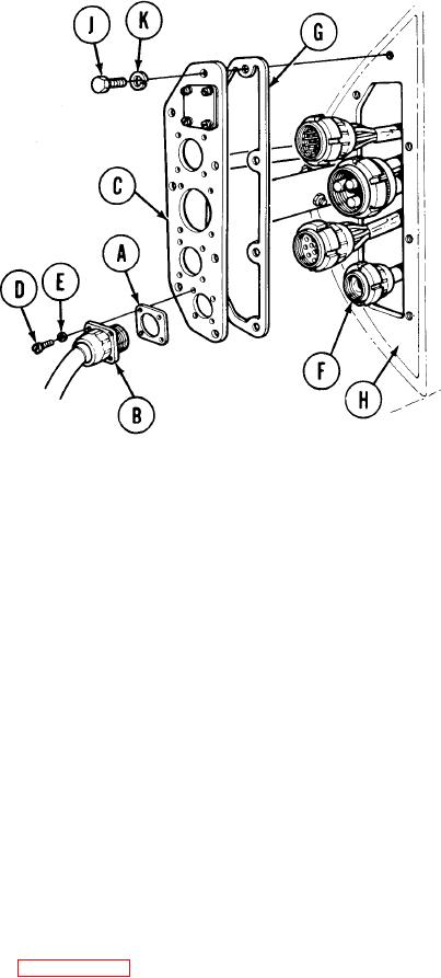
BULKHEAD CABLE DISCONNECT (Sheet 2 of 2)
NOTE
B u l k h e a d connectors are installed in
consecutive order from either bottom to
top or from top to bottom or the middle
connectors must be installed first, then
t h e top or bottom connectors.
The
instructions below are for installation
of the bottom connector first. Installa-
tion procedures are the same for all the
other connectors.
INSTALLATION:
Place gasket (A) on connector (B).
1.
Make sure keyway inside connector (B) is at top. Place connector (B) and gasket (A)
2.
in position on cover plate (C).
3.
Using flat-tip screwdriver, install four screws (D) and lockwashers (E) securing connector
(B) and gasket (A) to cover plate (C).
4.
Using fingers, install connector (F) on connector (B).
5.
When connector (F) is finger tight, use spanner wrench to finish tightening.
6.
Install succeeding connectors in consecutive order in same manner.
7.
After all connectors are installed, place cover plate (C) and gasket (G) in position on
bulkhead (H).
8.
Using 9/16 inch socket, install seven screws (J) and lockwashers (K) to secure cover
plate (C) to bulkhead (H).
Install right bulkhead access cover (page 17-3).
9.
10. Install commander's seat (page 17-79).
11.
Connect three ground straps at batteries (page 10-268).
TA249211
End of Task