
TM 5-5420-202-20-3
SHIFT CONTROL BRACKET AND LINK ASSEMBLY REPAIR (Sheet 8 of 11)
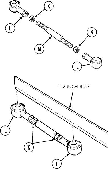
10.
Using fingers install nuts (K) and rod
ends (L) on stud (M).
NOTE
When adjusting clevises or rod
ends, make certain that
threads on control rods extend
past the witness hole in the rod
end to ensure a positive grip.
1.
Using two 9/16 inch wrenches and 6
inch rule, adjust rod ends (L) to obtain
the same center-to-center distance
between rod end holes as measured
and recorded in steps 3 and 4, DISASSEMBLY.
2.
Using torque wrench and crow foot adapter,
tighten nuts (K) against rod ends (L)
to 16-18 lb-ft (22-24 Nm).
Go on to Sheet 9
TA249314
11-48