
TM 5-5420-202-20-3
SHIFTING CONTROL BRACKET AND LINK ASSEMBLY REPAIR (Sheet 9 of 11)
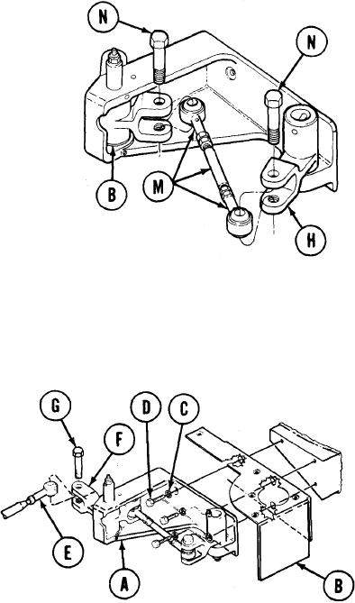
13.
Position stud and rod end bearing assem-
bly (M) with rod end holes alined with
the clevis holes in lever assembly (B)
and link assembly (H).
14.
Using 9/16 inch wrench, install two
bolts (N) through link assemblies (H)
and lever (B) and stud and rod end
bearing assembly (M).
15.
Using torque wrench and 9/16 inch socket,
tighten two bolts (N) to 15-20 lb-ft
(20-27 Nm).
INSTALLATION:
Position bracket assembly (A) and shield
1.
(B) against hull wall with mounting holes
alined.
2.
Using 9/16 inch socket and 5 inch extension,
install three lockwashers (C) and screws (D)
through bracket (A) and shield (B).
3.
Using torque wrench, tighten three
screws (D) to 15-20 lb-ft (20-27 Nm).
4.
Position rod end (E) in lever (F).
5.
Using 9/16 inch combination wrench,
install bolt (G) through lever (F) and
rod end (E).
6.
Using torque wrench, tighten bolt (G)
to 15-20 lb-ft (20-27 Nm).
Go on to Sheet 10
TA249315