
TM 5-5420-202-20-3
MECHANICAL TRACK ADJUSTING LINK REPLACEMENT (Sheet 5 of 5)
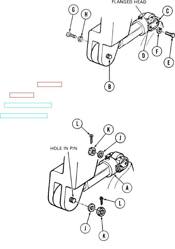
Aline flanged head of pin (C) with hole for
9.
screw (E). Insert screw (E) through washer
(F), flanged head of pin (C), and shim (D).
10. Using 3/4 inch socket, tighten screw (E).
Aline flanged head of pin (B) with hole for
11.
screw (G). Insert screw (G) through washer
(H) and flanged head of pin (B).
12. Using 3/4 inch socket, tighten screw (G).
13.
Using 1-1/8 inch socket, install both washers (J)
and nuts (K) onto pins (B) and (C).
14. Using pliers, install cotter pins (L) through
slots in nuts (K) and holes in pins (B) and (C).
15.
Install compensating idler wheels (page 14-53).
Install front fender (page 16-62).
16.
17.
Connect track (TM 5-5420-202-10).
18.
Adjust track (TM 5-5420-202-10).
End of Task
TA249585
14-58