
TM 5-5420-202-20-3
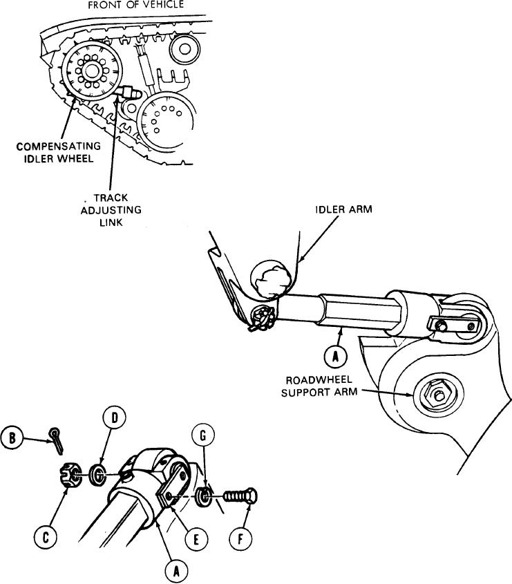
MECHANICAL TRACK ADJUSTING LINK REPLACEMENT (Sheet 2 of 5)
REMOVAL:
Using wire brush and rag, clean off both
1.
ends of adjusting link (A).
NOTE
Due to a configuration change,
link pin that secures adjusting
link to roadwheel arm was
reversed and is not installed
with threaded end toward huII
of vehicle.
2.
Using pliers, straighten cotter pin (B) and
remove it from slotted nut (C) at roadwheel
support arm.
Using 1-1/8 inch socket, remove nut (C) and
3.
washer (D) from pin (E).
Using 3/4 inch socket, remove screw (F)
4.
securing pin (E) to link (A). Rem
washer (G).
TA249582
GO on to Sheet 3