
TM 5-5420-202-20-3
MECHANICAL TRACK ADJUSTING LINK REPLACEMENT (Sheet 4 of 5)
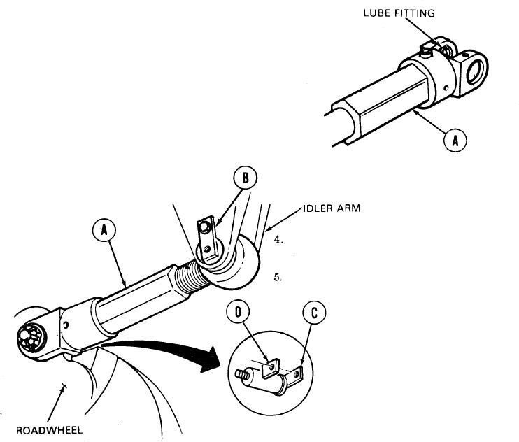
INSTALLATION:
Before mounting link (A), position it so lube
1.
fitting is on top (pointing outward).
Rotate arm until link mount is above slope
2.
at front of vehicle.
With help of second person, lift link (A)
3.
into mounted position on vehicle.
Aline pin (B) grooves with two splines in
bearing. Insert pin (B) toward hull side.
Using hammer, drive pin (B) into place
through link (A).
Lower arm and position other end of link (A) on mount at roadwheel.
6.
7.
Aline pin (C) with two splines in bearing. Insert pin (C) from outside.
Using hand to hold shim (D) in place between mount and pin (C), use hammer and drive pin (C)
8.
through link (A).
TA249584
Go on to Sheet 5