
TM 5-5420-202-20-3
TRACK SHOE PAD REPLACEMENT (Sheet 2 of 2)
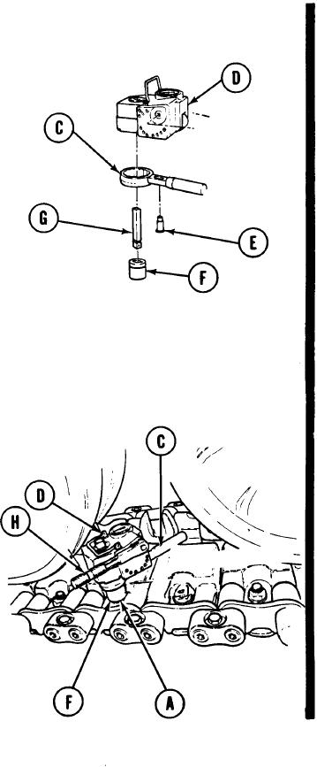
Position reaction lever (C) on torque pack
3.
(D) and secure using shoulder screw (E).
Place 1-1/8 inch socket (F) on drive bar (G)
4.
and install drive bar (G) into torque pack
(D).
Position torque pack (D) with drive bar (G)
5.
and socket (F) over center pad nut (A) to
be tightened.
6.
Install ratchet (H) on torque pack (D) and
rotate ratchet until socket (F) engages
center pad nut (A).
7.
Rotate ratchet (H) clockwise until torque
pack dial indicates 260-280 lb-ft (352-379
N m).
8.
Wait approximately 15 seconds, read dial,
and repeat step 7 until dial reading
stabilizes at 260-280 lb-ft (352-379 N m).
9.
Rotate ratchet (V) counterclockwise until
dial reading indicates 0. Remove torque
pack.
.
End of Task