
TM 5-5420-202-20-3
GREASE ACTUATED TRACK ADJUSTING LINK REPLACEMENT (Sheet 3 of 7)
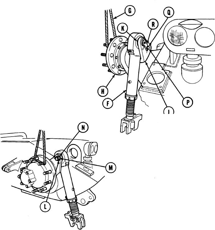
Attach wire rope assembly (G) to compen-
4.
sating idler wheel hub (H). Using lifting
device, raise compensating idler arm
(J) until adjusting link mounting eye
(K) is positioned above the front slope
of the tank.
5.
Position adjusting link (F) as shown.
6.
Using slip joint pliers, straighten and
remove cotter pin (L). Throw pin away.
7.
Using 1-1/8 inch socket, remove nut (M) and
washer (N).
8.
Using 3/4 inch wrench, remove cap-
screw (P) and lockwasher (Q) securing tab
on pin assembly (R) to imer face of com-
pensating idler arm (J). Throw lock-
washer away.
Go on to Sheet 4
TA250375
14-101