
TM 5-5420-202-20-3
GREASE ACTUATED TRACK ADJUSTING LINK REPLACEMENT (Sheet 5 of 7)
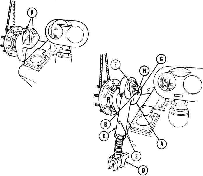
INSTALLATION:
1.
Put a light coat of grease on two
mounting eyes of compensating idler
arm (A).
Put a light coat of grease on pin
2.
assembly (B).
Using second person, position grease
3.
actuated track adjusting link (C) with
yoke (D) facing down and safety relief
valve (E) facing up as shown.
4.
Using second person, put adjusting link (C)
between two eyes of compensating idler
arm (A).
Align keyways in pin assembly (B) with
5.
splines in adjusting link bearing (F) and
install pin assembly (B) from hull side to
secure adjusting link (C) to compensating
idler arm (A).
6.
Align tab on pin assembly (B) with threaded hole in compensating idler arm (A) and install
capscrew (G) and new lockwasher (H). Using 3/4 inch wrench, tighten capscrew (G).
Go on to Sheet 6
TA250377