
TM 5-5420-202-20-3
GREASE ACTUATED TRACK ADJUSTING LINK REPLACEMENT (Sheet 6 of 7)
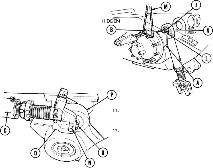
Install flat washer (J) and nut (K) on
7.
threaded end of pin assembly (B).
8.
Using 1-1/8 inch socket, tighten nut (K)
and align slot in nut (K) with hole in pin
assembly (B).
Using pliers, install new cotter pin (L).
9.
Using wire rope assembly (M) and lifting
10.
device, lower compensating idler arm (A).
Aline slots of yoke (D) on adjusting
link (C) with bearing (N) on number 1
roadwheel support arm (P).
Using 15/16 inch socket and extension,
install and tighten two capscrews (Q) to
secure adjusting link (C) to bearing (N).
13.
Using torque wrench, tighten capscrews (Q)
150-200 lb. ft. (203-271 N<m).
14.
Remove wire rope assembly (M) and
lifting device.
Go on to Sheet 7
TA250378
14-104