
TM 5-5420-202-20-3
GREASE ACTUATED TRACK ADJUSTING LINK REPAIR (Sheet 4 of 4)
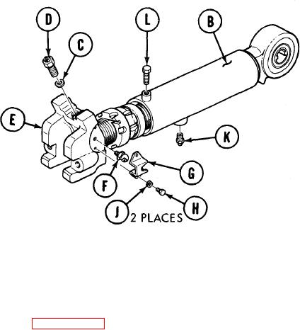
Put thin coat of grease on new
3.
packing (C).
4.
Install new packing (C) and pressure relief
valve (D) in yoke (E).
5.
Using 0-175 foot-pound torque wrench and
15/16 inch socket, torque valve (D) be-
tween 40-60 pound-feet (54-81 N.m)
6.
Using 7/16 inch socket, install grease
fitting (F) in yoke (E).
7.
Position support link assembly (G) on yoke (E). Using 7/16 inch socket, install two screws
(H) and new lockwashers (J).
8.
Using 7/16 inch socket, install safety relief valve (K) in adjusting link (B).
9.
Install locking collar screw (L) in adjusting Iink (B), but do not tighten.
10.
Install grease actuated track adjusting link (page 14-103).
End Of Task
TA250382
14-109/(14-110 blank)