
TM 5-5420-202-20-3
STEERING CONTROL LINKAGE ADJUSTMENT (Sheet 11 of 22)
52.
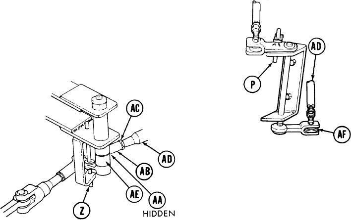
With locating pin (P) still installed, try to
insert locating pin (Z). If locating pin (Z)
can be inserted, go on to step 75. If locating
pin (Z) cannot be inserted, go on to step 53.
DRIVER'S STATION
53.
U s i n g 9/16 inch wrench, remove screw
(AA).
54.
Move link assembly and insert locating pin
(Z).
LEFT OF DRIVER'S STATION
Using 9/16 inch wrench to hold steering
55.
rod end (AB), use 9/16 inch wrench to -
loosen jamnut (AC).
56.
Using 9/16 inch wrench, adjust length of control rod (AD) by turning steering rod
end (AB) clockwise or counterclockwise until screw (AA) will drop freely through
clevis (AE) and steering rod end (AB).
57.
Using small gage wire, check to see if control rod (AD) is into steering rod ends (AB)
and (AF) past witness holes. If control rod (AD) is past witness holes in both steering
rod ends (AB) and (AF), go on to step 72. If control rod (AD) is not past witness hole
in steering rod end (AB), go to step 58. If control rod (AD) is not past witness hole
in steering rod end (AF) go on to step 68.
TA249664
G O on to Sheet 12
15-41