
TM 5-5420-202-20-3
STEERING CONTROL LINKAGE ADJUSTMENT (Sheet 12 of 22)
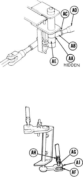
58.
Using 9/16 inch wrench, turn steering rod
end (AB) clockwise until control rod (AD)
is just past witness hole in steering rod
end (AB).
59.
Using 9/16 inch wrench to hold steering
rod end (AB), use 9/16 inch wrench to
tighten jamnut (AC).
60.
U s i n g 9/16 inch wrench, remove screw
(AG).
61.
Position steering rod end (AB) in clevis
(AE) and using 9/16 inch wrench, install
screw (AA).
62.
Using torque wrench and crowfoot, tight-
en screw (AA) to 16 lb-ft (22 N.m).
63.
Using 9/16 inch wrench to hold steering
r o d end (AF), use 9/16 inch wrench to
loosen jamnut (AH).
Using 9/16 inch wrench, turn steering rod
64.
e n d (AF) counterclockwise until screw
(AG) will drop freely through clevis (AJ)
and steering rod end (AF).
DRIVERS STATION
Go on to Sheet 13
TA249665
15-42