
TM 5-5420-202-20-3
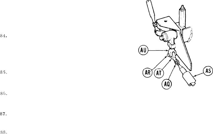
STEERING CONTROL LINKAGE ADJUSTMENT (Sheet 16 of 22)
Using small gage wire, check if control
rod. (AS) is past witness hole in steering
rod end (AT). If control rod (AS) is past
witness hole, go on to step 85. If control
rod (AS) is not past witness hole, go on to
step 88.
U s i n g 9/16 inch wrench to hold steering
r o d end (AT), use 9/16 inlch wrench to
tighten jamnut (AQ),
P o s i t i o n steering rod end (AT) in clevis
LEFT SIDE OF HULL
(AU) and using 9/16 inch wrench, install
(TO REAR OF FUEL TANK)
screw (AR.).
Using socket and torque wrench, tighten screw (AR) to 16 lb-ft (22 N.m).
Go on to step 109.
Using 9/16 inch wrench, turn steering rod end (AT) clockwise until control rod (AS)
is just past witness hole in steering rod end (AT).
Using 9/16 inch wrench to hold steering rod end (AT), use 9/16 inch wrench to tighten
jamnut (AQ).
TA249669
Go on to Sheet 17
15-46