
TM 5-5420-202-20-3
STEERING CONTROL LINKAGE ADJUSTMENT (Sheet 14 of 22)
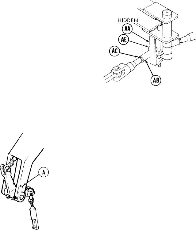
71.
Using 9/16 inch wrench, turn steering rod
end (AB) counterclockwise until screw
(AA) will drop freely through clevis (AE)
and steering rod end (AB).
72.
U s i n g 9/16 inch wrench, install screw
(AA).
73.
Using torque wrench and crowfoot, tight-
en screw (AA) to 16 lb-ft (22 N.m).
LEFT OF DRIVER'S STATION
Using 9/16 inch wrench to hold steering rod end (AB), use 9/16 inch wrench to tighten
74.
jamnut (AC).
NOTE
Do not remove locater pins already
installed.
75.
Try to insert locating pin (A). If locating
pin (A) can be inserted, linkage is in adjust-
ment. Go on to step 128. If locating pin
(A) cannot be inserted, remove powerplant
(page 5-2) and go on to step 76.
LEFT SIDE OF TRANSMISSION
Go on to Sheet 15
TA249667
15-44