
TM 5-5420-202-20-3
STEERING CONTROL LINKAGE ADJUSTMENT (Sheet 18 of 22)
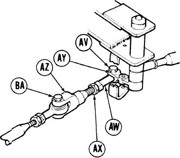
97.
U s i n g 9/16 inch wrench, install screw
(AV).
Using
98.
wrench and
crow foot,
tighten screw (AV) to 16 lb-ft (22 N.m)
and go on to step 109.
Using 9/16 inch wrench, turn steering rod
99.
end (AW) clockwise until control rod (AZ)
is just past witness hole in steering rod
end (AW).
100.
Using 9/16 inch wrench to hold steering
r o d end (AW), use 9/16 inch wrench to
tighten jamnut (AX).
101,
Using 9/16 inch
wrench, r e m o v e screw
(BA).
102.
Position steering rod end (AW) in clevis
LEFT OF DRIVER'S STATION
(AY) and using 9/16 inch wrench, install
screw (AV).
103.
Using
wrench and
crow foot,
tighten screw (AV) to 16 lb-ft (22 N.m).
Go on to Sheet 19
TA249671
15-48