
TM 5-5420-202-20-3
STEERING CONTROL LINKAGE ADJUSTMENT (Sheet 20 of 22)
111.
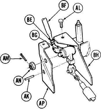
Using hands, turn control rod (BF) clock-
wise until control rod (BF) is just past
witness hole in steering rod end (BG).
112.
Using 9/ 16 inch wrench to hold steering
rod end (BG), use 9/16 i n c h wrench to
tighten jamnut (BE).
113.
Remove locating pin (AK).
114.
Position plate (AP) on plate (BH).
115.
U s i n g 9/16 inch wrench,
i n s t a l l screw
(AL).
LEFT SIDE OF HULL
(TO REAR OF FUEL TANK)
116.
Using 3/4 inch wrench, install nut (AN).
Using pliers, install cotter pin (AM) through nut (AN).
117.
Install powerplant (page 5-2).
118.
Go on to Sheet 21
TA249673
15-50