
TM 5-5420-202-20-4
REAR DRAIN VALVE LINKAGE ADJUSTMENT (Sheet 4 of 7)
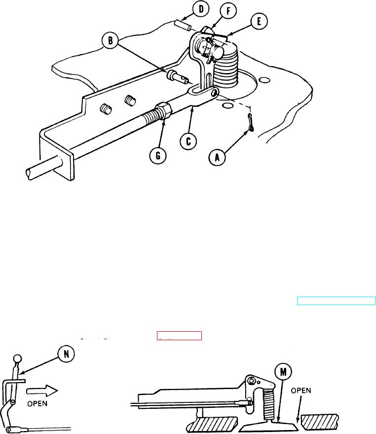
If clevis pin (B) was not installed in clevis (C) in step 12, use fingers and install clevis
14.
pin (B) in holes in clevis (C) and hole in lever (E).
Using pliers, install new cotter pin (A) in clevis pin (B).
15.
Pull alinement pin (D) out of hole in lever (E) and hole in bracket (F).
16.
17.
If clevis jamnut (G) was not tightened against clevis (C) in step 10, use wrench and tighten
jamnut (G) while holding clevis (C) with pliers.
Make sure drain valve (M) opens when control lever (N) is in open position (TM 5-5420-202-10).
18.
If valve (M) does not open, perform steps 19 through 30.
If valve (M) opens, go to step 31 (page 17-46).
TA248574
Go on to Sheet 5
17-43