ARMY TM 5-5420-212-10-1
MARINE CORPS TM 08676A-10/1-1
(4)
Fit nose cross girder posts to junction panels (para. 4-11b.).
(5)
Fit nose cross girder to post at correct height and put retainer clips through the end of captive pins (para.
4-11c.).
(6)
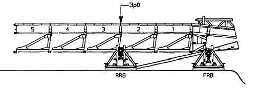
Add bays 2 and 3. Do not add sway braces.
(7)
Assemble launching nose (6N1) with landing roller pedestal (para. 4-12b.).
(8)
Place one deck unit in the third deck recess of bay 1. Pin sway braces in bays 1,2 and 3.
(9)
Add bays 4 and 5. Add sway braces to bays 4 and 5.
CAUTION
The following cautions should be observed each time the bridge Is boomed. Do not allow vehicle
to drift right or left of centerline. Keep vehicle straight and in line with bridge. Movement of bridge
to right or left can cause damage to roller beams.
NOTE
Throughout the build the bridge Is boomed using a vehicle, push bar and push bar cross girder
(para. 4-18) which must be disconnected before further bays are added. To simplify the following
procedures these drills are described "connect push bar" and "disconnect push bar."
(10) Connect push bar. Unlock rollers and boom bridge to panel point 3p0 (over RRB). Lock rollers, and
disconnect push bar.
(11) Add bays 6, 7 and 8. Add sway braces to bays 6, 7 and 8.
(12) Place one deck unit in the third deck recess of bay 7. Placement of deck unit in bay 7 will keep girders of
bridge spaced at correct distance.
(13) Connect push bar. Unlock rollers. Boom bridge to panel point 4p4 (over RRB). Lock rollers, and
disconnect push bar.
6-30


