ARMY TM 5-5420-212-10-1
MARINE CORPS TM 08676A-10/1-1
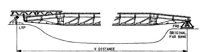
(Not to be greater than distance tabulated, eg. See TM 5-5420-212-10-2)
(4)
Assemble and position rear roller beam.
(5)
Complete assembly of launching nose.
(6)
Connect vehicle and push bar to near bankseat beam.
(7)
Using landing roller pedestal, raise bridge off ground until jack is fully extended.
NOTE
Vehicle is holding bridge and rollers are locked.
(8)
Delaunch bridge and position rear roller beam under the rear of the bridge. Position RRB using
longitudinal girders, then disconnect girders from RRB and place on the ground.
(9)
Level both roller beams.
(10) Continue delaunch to panel point 5p6 (over front roller beam).
CAUTION
The center of gravity of the bridge is over the front roller beam. It is at this point that any minor
adjustments in the rear roller beam placement must be made. Ensure that the bridge will come to
rest on the roller beams correctly. The bridge should rest between the flanges of the rollers, not
on top of them.
(11) Recover landing roller pedestal.
(12) Continue delaunch to panel point 6pl (over rear roller beam).
WARNING
Safety packing under the bridge in front of the front roller beam is used as a safety stop to prevent
loss of the bridge during the removal of bridge bays. Safety packing will be put in after step (12)
and will remain in place until the last boom is made.
(13) Place safety packing in front of front roller beam. Stack packing between front roller beam and the edge
of gap and keep height of packing within 3 in (7.5 cm) of bottom of bridge girder. If minimum bearing
has been used, place packing inside FRB baseplates under the bridge girder.
6-41