ARMY TM 5-5420-212-10-1
MARINE CORPS TM 08676A-10/1-1
(14) Remove end of bridge.
(15) Remove junction panel (para. 4-27a.).
CAUTION
For all booms/delaunches with the vehicle, before connecting the push bar cross girder and push
bar, ensure the last bottom panel top jaws are still located round the panel pin.
(16) Boom bridge to 4p6 (over rear roller beam).
(17) Remove deck unit in bay 11 then remove bay 12, bay 11 and bottom panel of bay 10 (para. 4-27b and
c.).
(18) Boom bridge to panel point 3p6 (over rear roller beam).
(19) Remove top panel 10, bay 9 and bottom panel 8.
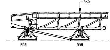
(20) Boom bridge to panel point 3p0 (over rear roller beam).
(21) Remove deck unit in bay 7, then top panel 8, bottom panel 7, top panel 7 and bottom panel 6.
NOTE
Additional booms to panel point 1p7 and 2p0 are required to ease the removal of the last four
bottom panels and the pin in the last top panel and junction panel.
(22) Boom bridge to 1 p7 over rear roller beam. Disassemble the bridge until the top panel in bay 4 is
reached. DO NOT REMOVE BAY 4 TOP PANEL.
6-42


