ARMY TM 5-5420-212-10-1
MARINE CORPS TM 08676A-10/1-1
(23) Remove the launching nose.
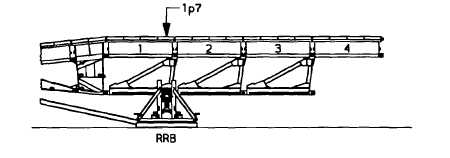
(24) Boom bridge to panel point 2p0 (over rear roller beam). This boom is needed to make the removal of
the pin at "A" easier.
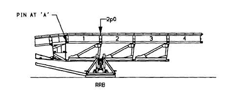
NOTE
The panel pin In the upper pin jaws of the junction panel and last top panel is called the pin at "A."
This panel pin must be removed before the top panel of Bay 4 can be removed. The removal of
the pin at "A" serves the same purpose as unlocking the bottom panel shoot bolt.
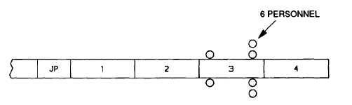
(25) To remove the pin at “A” position six personnel around the rearmost bottom panel, and lift, then remove
pin.
(26) Boom bridge to panel point lp4 (over rear roller beam).
(27) Remove remaining bays of bridge until bottom panel 2 is removed. Remove deck unit in bay 1.
(28) Position 16 personnel (right and left side crews) around end of bridge.
6-43