ARMY TM 5-5420-212-10-1
MARINE CORPS TM 08676A-10/1-1
(19) Disassemble rear roller beam and front roller beam. Do not allow personnel to work under bridge.
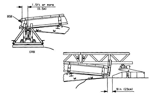
(20) Continue launch until the far bank bankseat beam is within 9 in (23 cm) of landing roller pedestal base.
The near bank end of bridge should be1.5 ft (0.5 m) or greater from center of the capsill roller beam
rollers.
(21) Lock capsill roller beam rollers.
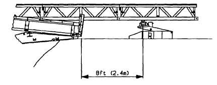
(22) Lower far bank end of bridge by operating jack in landing roller pedestal. Reposition landing roller
pedestal so the center of roller is 8 ft (2.4 m) from nose roller on bankseat beam. Raise landing roller
pedestal until roller touches bottom of launching nose.
(23) Disconnect vehicle and push bar from bridge.
(24) Remove remaining launching nose heavy sections (para. 4-13c) and launching nose roller (reverse of
para. 4-10).
(25) Remove launching nose cross girder and nose cross girder posts (para. 4-11).
(26) Distribute deck units and curbs from counterweight to their final positions and remove curbs from
bankseat beam to enable jacking brackets to be fitted if davits are to be used.
6-48


