ARMY TM 5-5420-212-10-1
MARINE CORPS TM 08676A-1011-1
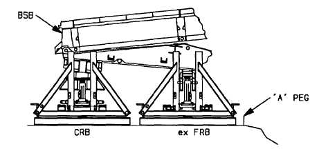
(55) Raise ex FRB to its maximum safe height.
(56) Lower capsill roller beam until the bridge rests on rollers of ex FRB.
(57) Ensure ex FRB rollers are unlocked (vehicle is holding bridge).
(58) Remove capsill roller beam from under the end of bridge and disassemble.
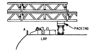
(59) Reposition the landing roller pedestal.
NOTE
If two landing roller pedestals are not available, use procedures (a) thru (f). If two are available,
use procedures (g) thru (i).
(a)
Place one launching nose heavy section under nose. Nose section is placed perpendicular to the
launching nose and against base at the rear of the landing roller pedestal.
(b)
Place two pieces of packing on top of nose section to protect the edges of nose section.
(c) Operate hydraulic jack to lower the launching nose onto the packing and nose section.
(d)
Remove the landing roller pedestal and relocate it under the launching nose so the base of it is 12 ft
(3.7 m) from the A peg.
(e)
Operate hydraulic jack to it’s maximum height.
7-22


