
TM 5-5420-226-20-2
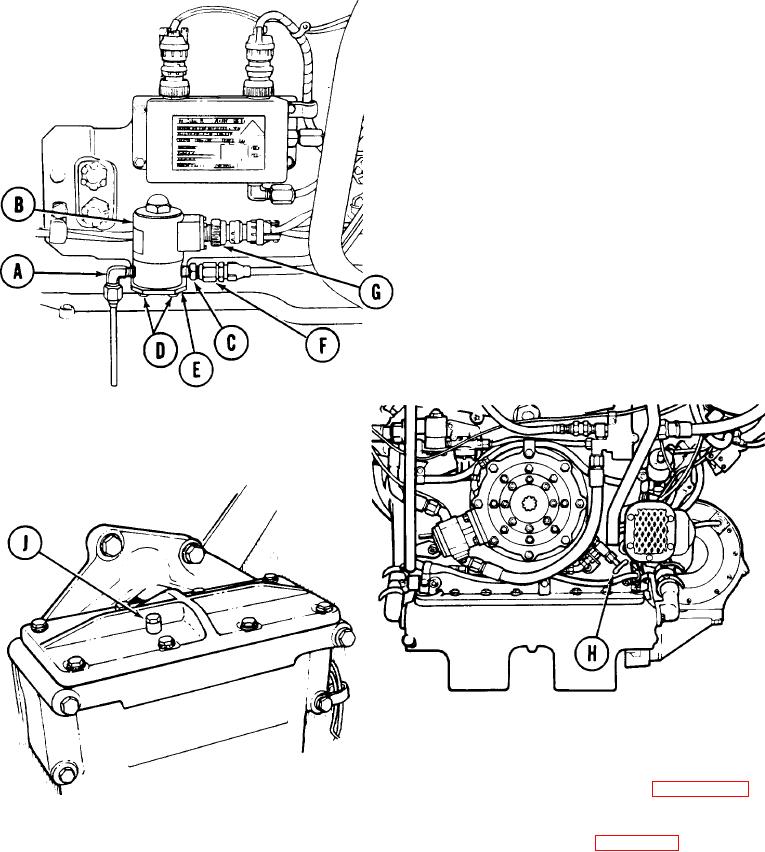
FUEL-WATER SEPARATOR DRAIN SOLENOID VALVE REPLACEMENT (Sheet 3 of 3)
NOTE
INSTALLATION:
Coat all exposed threads of
adapter and elbow with zinc-
chromate (Item 51, Appendix
D) before installing.
Using 9/16 inch wrench, install elbow
1.
and tube (A) to solenoid valve (B).
Using 9/1 6 inch wrench, install adapter
2.
(C) in. solenoid valve (B).
Position solenoid valve (B) to bracket.
3.
Using 5/16 inch wrench, install two
4.
screws and lockwashers (D) to secure
solenoid valve (B) to bracket (E).
Using two 9/16 inch wrenches, connect
5.
hose assembly (F) to adapter (C).
Connect electrical lead (G) to solenoid
6.
valve (B).
Close drain valve (H) by turning
7.
valve handle clockwise.
Using 7/16 inch wrench, turn bleed
8.
cap (J) clockwise until snug.
Test fuel-water separator (page 7-230,
9.
steps 1 thru 11).
Install powerplant (page 5-14).
10.
TA10783O
End of Task
7-223