
TM 5-5420-226-20-2
FUEL-WATER SEPARATOR CONTROL ASSEMBLY REPLACEMENT (Sheet 4 of 5)
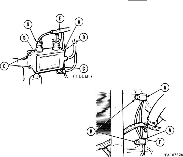
INSTALLATION:
1. Install three cushioned clamps (A) onto sensor leads from replaced fuel-water
separator control assembly (B).
Position fuel-water separator control
2.
assembly (B) onto mounting plate.
3. Using 5/16 inch wrench, install
three screws and washers (C).
4. Using 5/16 inch wrench, install screw (D)
and cushioned clamp (A) holding solenoid
valve electrical lead (E) to fuel-water
separator control assembly (B).
CAUTION
Be careful not to strike
ends of sensors during installa-
tion or damage may result.
NOTE
Straight edge of mounting
plate (F) must be installed
to the right against the fuel
water separator.
Manually connect solenoid valve elec-
5.
trical lead (E) to fuel-water separator
control assembly (B).
Manually connect engine electrical
6.
harness connector (G) to fuel-water
separator control assembly (B).
7. Using screwdriver, install two screws
(H), two cushioned clamps (A), and mounting
plate (F) at right side and above fuel-
water separator control assembly.
Go on to Sheet 5