
TM 5-5420-226-20-2
FUEL-WATER SEPARATOR OPERATIONAL TESTS (Sheet 3 of 11)
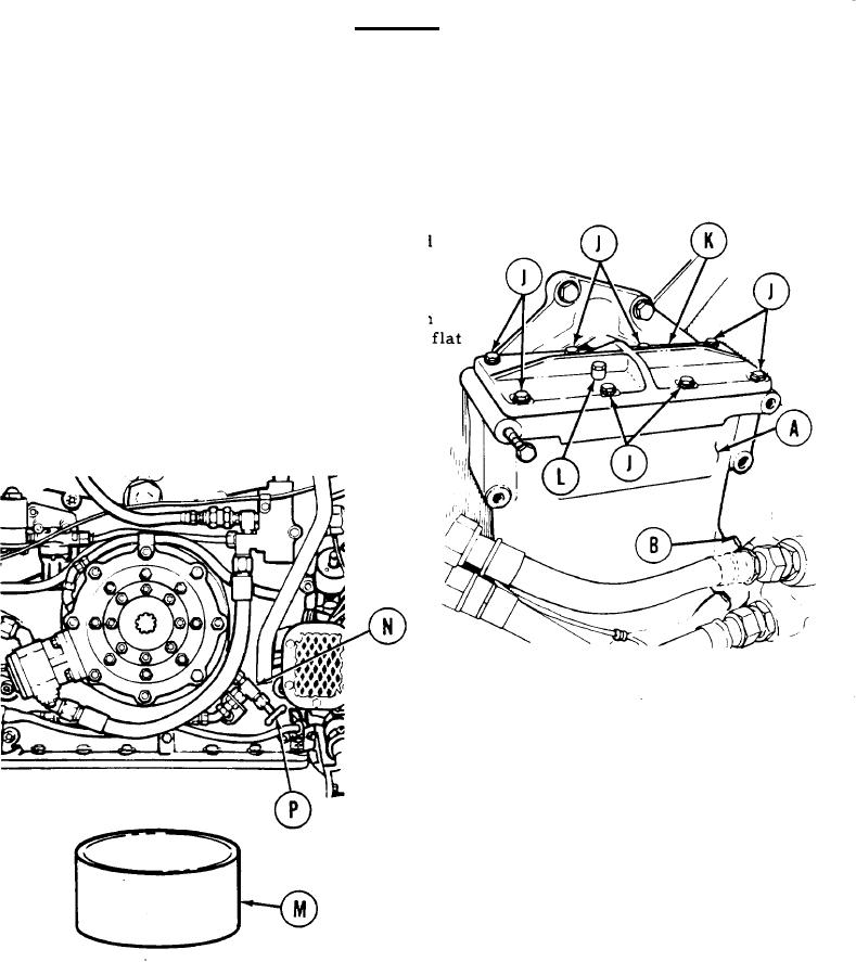
Manual Drain Test (Sheet 2 of 2)
CAUTION
There is a gasket located between fuel-water separator
cover and fuel-water seperator body. Each time cover
is removed care must be taken not to disturb gasket.
If fluid level in fuel-water separator (A) is not
10.
above upper sensor probe (B) hole, using 7/16 inch
wrench, remove eight screws, lockwashers, and
flat washers (J) securing cover (K) to separator (A).
11.
Add fuel to fuel-water separator (A) until fluid
level is above upper sensor (B) hole.
Place cover (K) in position and, using 7/16 inch
12.
wrench, install eight screws, lockwashers, and f
washers (J).
13.
Using 7/16 inch socket, open bleed cap (L)
by turning counterclockwise.
14. Place metal container (M) under outlet
of manual drain valve (N).
15. Open manual drain valve (N) by turning
petcock (P) counterclockwise. Allow small
amount of fluid to drain into metal container (M).
16. If fluid does not drain, refer to troubleshooting
procedures,
17. If fluid does drain, go on to automatic drain test
on next page.
Go on to Sheet 4
TA107839
7-232